
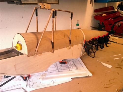
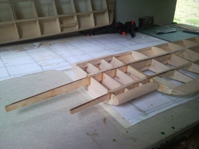
Those little tiny clamps are really, really useful.
Not sure how I should have clamped the front half of the top ply. There’ s quite a lot of glue escaped. Very thin ply (nice peice of ply Eddie) just overlapped onto the balsa sides. Difficult now to smooth down.
It’s the cowl next.
The instructions suggest glueing the two halves together, but I’m not sure what sort of glue to use. I think it’s ABS plastic.
I though of just taping the two halves together and using them as a mould for making a fibreglass cowl. I’ve never done much fibreglassing but I’ve got a small kit, so that might be fun.
What do people suggest?
Put clear tape aka stickyback plastic aka sellotape over the join, on the outside, fold the two halves open, run a THIN thread of GORILLA glue along the edge, fold it shut, and wait three hours (+/-). Gorilla glue foams up as it cooks, so self-fills any gaps, (hence the clear tape on the outside!)
Gorilla glue sticks just about anything to anything, including fingers!, but doesn’t attack plastics or foam. If you get a run, it can be scraped off with an old credit card or blunt knifeblade, before it goes off.
I’ve heard about this ‘Gorilla Glue’ stuff, but haven’t got any.
StillI tempted to tape the two halves together and using them as a mould for making a fibreglass cowl. I’ve never done much fibreglassing but I’ve got a small kit.
What do people think of that idea? Would I need a releasing agent? Would I be able to buy a replacement cowl from DB if I screw up?
I followed the instructions, and glued the two halves of the cowl together, then reinforced with an extra strip of plastic on the inside of the join. I used some canopy glue I’ve got that says it’s OK for ABS plastic. Looks good but I’ve got a bit of a seam down the middle that doesn’t seem to want to sand out.
Just gone and bought an engine to put in it. I’ve treated myself to a Saito 72. Looks absolutely beautiful, but rather large (well, very large).
The instructions for the Moth just say something like ‘Install the engine’, and then elsewhere say something similarly unspecific like ‘plan the servo layout’. I’d have liked a couple of pictures or ideas for servo layout. The rudder and elevator lie straight but the throttle one has to travel an awkward route. Don’t know whether to lay the servo flat, and bend the wire, or lay the servo at an angle that allows a straight(ish) piece of wire. But then, as I’ve said before, it’s not a beginners model and I’m enjoying the challenge. It’s all part of the fun.
The kit includes all the parts for a closed-loop set-up for the throttle. I’d like to go down that route but can’t quite picture what to do with it. If anyone has any links to any photos of what other people have done I’d be grateful.
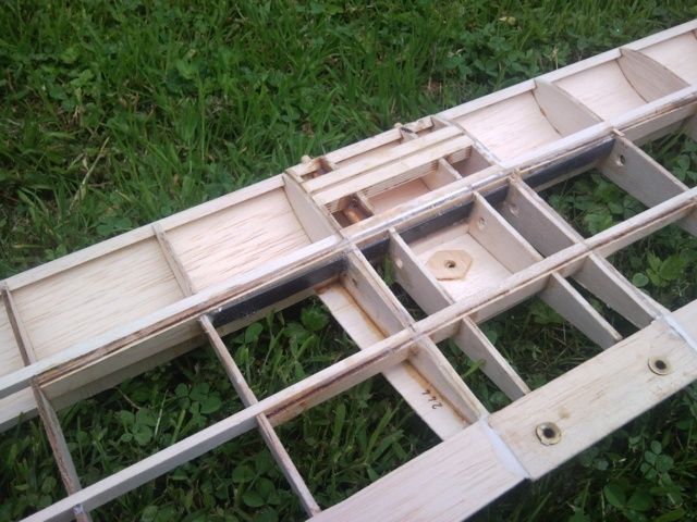
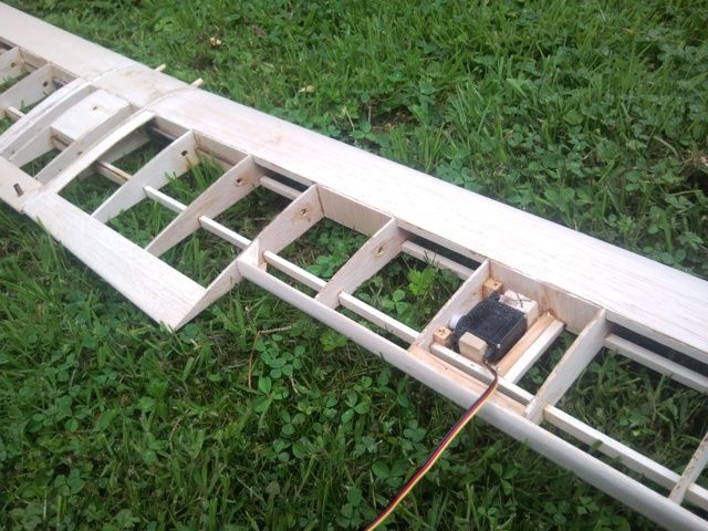
I’ve now set the servos in place.
– First the throttle, set at an angle so the wire, running through a piece of plastic tube, goes in a straight line to the throttle arm, which I’ve turned 180deg.- Next the rudder, which actuates a small aluminium bar which pivots on a piece of ply just behind the servo. This bar will, eventually, have the two wires attached for the closed-loop rudder control. If this doesnt work I can always rip it out and go direct from the servo!- Thirdly the elevator. This is likely to have a snake run down the fuselage, when I get one.I did take a photo but it didn’t work, I’ll take another tonight. Q’s.- Would you people still recommend a balsa push-rod for the elevator, or do you go for the more modern snakes?- If you like the snakes would you not also go for snakes for the rudder? Maybe two snakes for closed-loop control? – What about aileron control (months away at the snail-like speed I’m building at). The plans suggest a
metal rod from a single, common servo. Would people use snakes here? – Eddie, would you suggest one servo in the middle, or two, one in each wing?
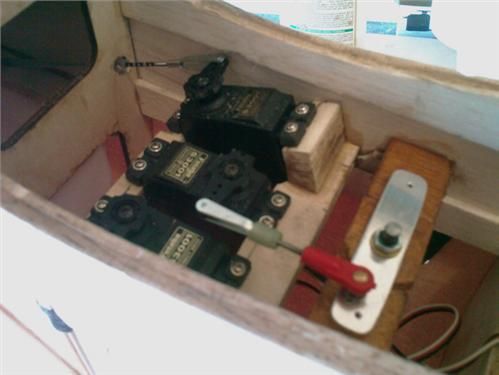
This is how I’ve got the servos.
– throttle , top in picture, port side of fuselage, at an angle.
– rudder running pivoting bar.
– elevator running snake (not fitted yet)
Any comments or criticisms, make them quick, before I go much further.
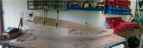
Just testing the ‘panoramic’ function I just found on my camera. Lets you take 3 photos then joins them up to make one long one.
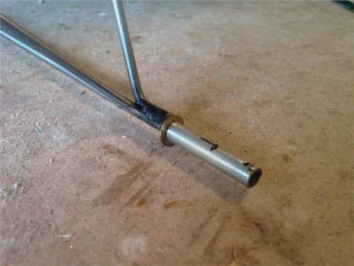
Quite pleased with the axle build.Welded the bars together, araldited a washer and tube on to the axle itself, and drilled a hole near the end of the tube for a split-pin..
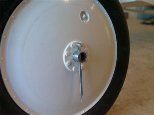
Had to ream out the hole in the wheal just a tiny bit, to suit the tube O/D.
But I think that looks rather good.
No doubt there are other ways you old-timers would have done it different.
Comments always welcome.
Now learning how to fit the covering.
I wanted to wait and get a photo of the whole build in wood, before covering. But at the speed I’m going that may be some while yet.
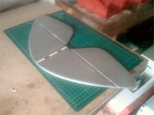
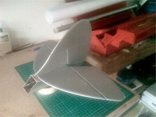
I’ve finished the tail assembly so I’ve been covering that this weekend. And it’s actually come out really, really nice.
Only mistake here (I shouldn’t keep mentioning my mistakes; people will think I’m rubbish at this !) was on one surface of the elevator;- it was harder to stick down than the others, and it’s come out a little ‘bubbly’. Even where there shouldn’t be any bubbles at all. I can only think that I forgot to remove the protective plastic film from the sheet. But then I wouldn’t have done that because that would be really stupid !!!
I did have trouble with the mylar hinges. I trial fitted them all together (six in total). Then glued all six into the elevators. Then trial fitted again. Then put glue on the remaining halves, than had a mad panic struggle as one of them wouldn’t go in, as the other five were setting, very quickly. Rather than have all six stick only half-in I decided to push the five all the way in, and deal with the errant one later.
Seems to have worked fine in the end, but a bit of a panic at the time.
Rudder I did last, and therefore it went really well.
The fin was more difficult because of the concave front edge. I naïvely assumed that the covering would shrink round the curve, but of course it wanted to shrink to a straight line and not touch the leading edge of the wood at all. In the end I split it with a knife, and wrapped each side round the leading edge a little.
The rudder is hinged to the fin in two places, and there is also a hinge to go into the back of the fuselage itself. Not sure how that’ll work but it looks like it should go fine. That’ll be after the fuselage is fully covered and the whole tail assembly gets glued on.
Tail and wings are going to be silver. Not sure about the fuselage colour yet.
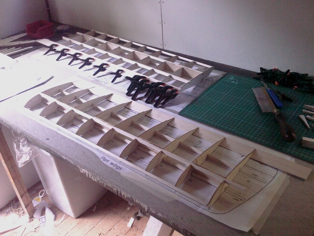
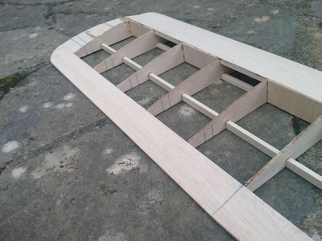
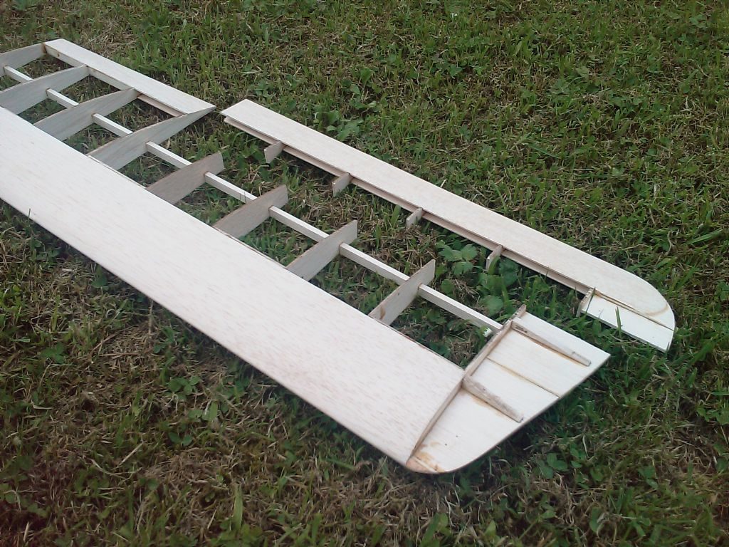
I’m finding I can do two wings at once on my bench. Other pair willhave to wait.

I obviously cut off the leading edge as well !
Time for a biscuit before I go any further.
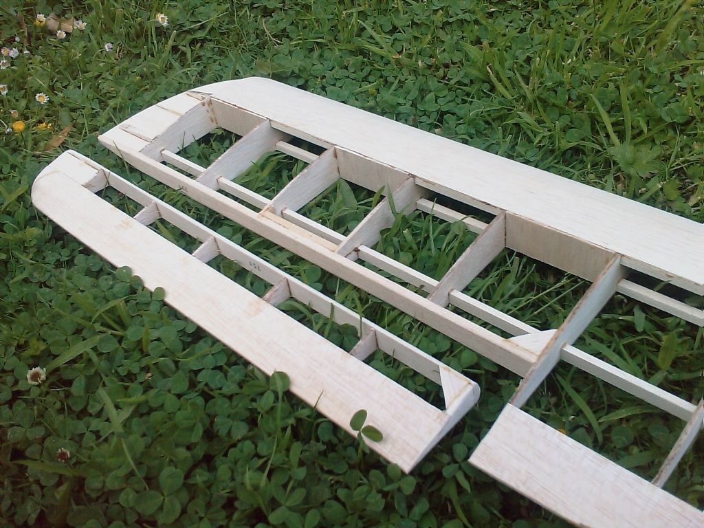
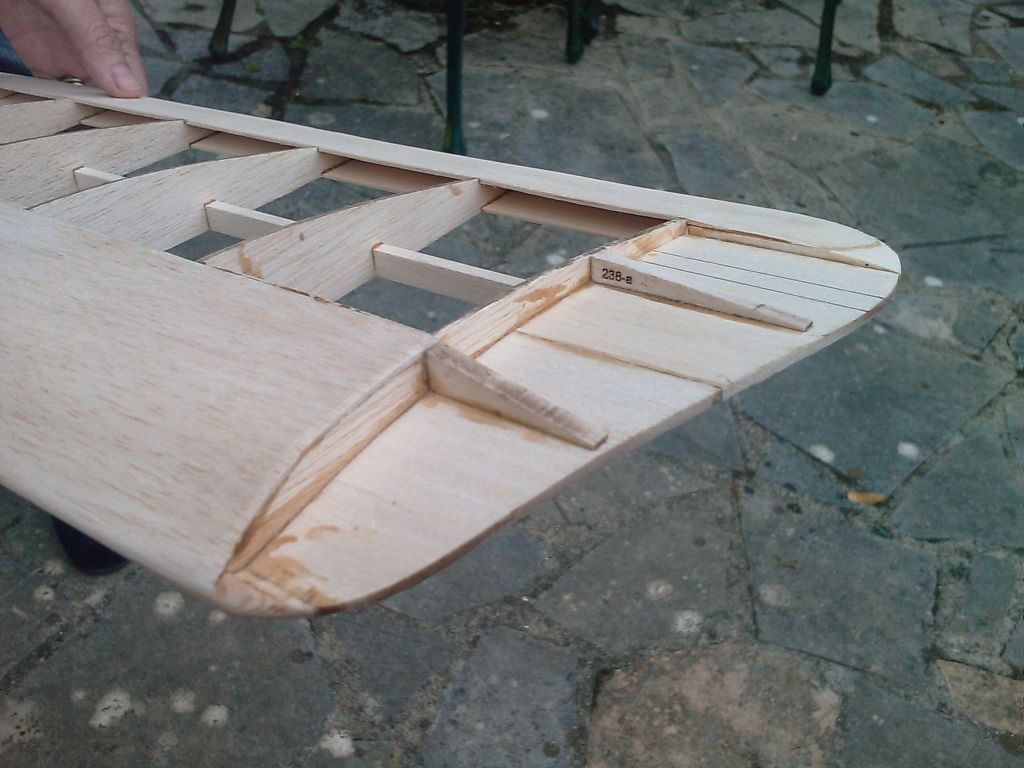
Also shows the small holes in the ribs for the servo wire. Think I’ll have to cut the wire and solder a join.
Glued to center section, showng ailerons cut out.