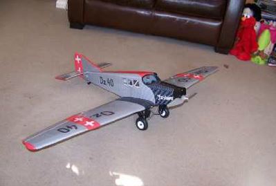
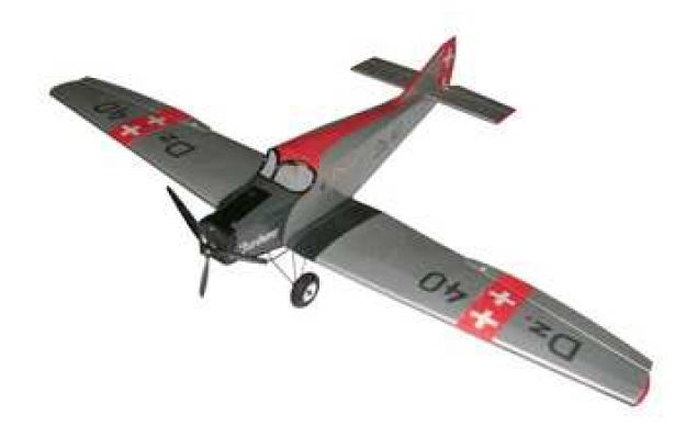
VMAR MODELS JUNKERS F-13 ARF ELECTRIC
13.3.2010
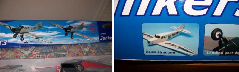
I collected the model from Channel 4 models, Bournemouth, after only ordering it a week ago so things bwere off to a good start. On returning home the kettle was put on and the box opened to see what goodies lay within.
The first thing that struck me was the packaging, screwed up newspaper was stuffed in the box to take up any space between the cardboard dividers, well I suppose we are all into recycling now but I was surprised to find it in a model box. The fuselage, wing and all metal parts are separately packed in plastic bags and looked present and correct, all control surfaces are pre-hinged and the areas for the control horns are prepared by having the film cut out where they will be glued into place, a nice touch. The brushless motor and esc are also pre-installed.
Pre-cut film for horn fitting, nice!
So let’s have a look at the destructions, firstly two A4 sheets of paper in 4 different languages explain that “this is not a toy “and all the usual health and safety blurb. That out of the way the “assembly and operations manual” is an attractive glossy colour 12 page booklet with a picture of the finished model on the front. All the instructions are very clear and easy to follow with exceptionally good quality photo’s to guide you on each step of the build all in English (no ‘chinglish’ to get your head around) and only one set of photos which are wrong, but we will get to that later.
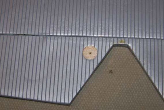
Starting off with the wing, the aileron horns are the first thing to install. Using a combination of thin CA and epoxy this is straight forward enough. At this point I found some damage to the upper part of the wing, two scratches which are purely cosmetic but I like to put my on scratches on if you know what I mean?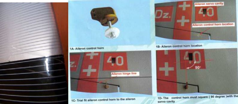
Next is to fit the aileron servo’s, this is where there is a bit of an error in the instructions. It reads ‘turn the wing upside down and install one servo first then the second servo’, then in the next step it says ‘Trial fit the aileron servo into the servo mounting cavity’ and so on. Surely this should be the other way around because if your building the plane as you follow the instructions you have already fitted them in the last step? In reality this isn’t a problem but would be nice to have it correct for the new builders amongst us.
No string is threaded through the cable runs to help pull the servo lead through, but there is a tube so it not too much hassle. Servo’s fitted; it’s on with the control rods next. The control rods are of plastic pushrod type with threaded bar stuck inside and aluminium clevises screwed on the end which have a screw to go threw the control horn. I personally don’t like these because there are a lot of bits stuck together to make what could be a simple threaded rod with nice metal clevises on each end. Be very careful when fitting the screw through the horn, if your not quite lined up with the thread on the other side of the clevis when you tighten it, it will spread the clevis and we all know what happens when you bend aluminium right? So be careful.
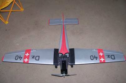
The instructions then go on to tell you how to set up the ailerons in good detail. Next I fitted the tail skid; the pictures in the instructions are incorrect as you can see below.
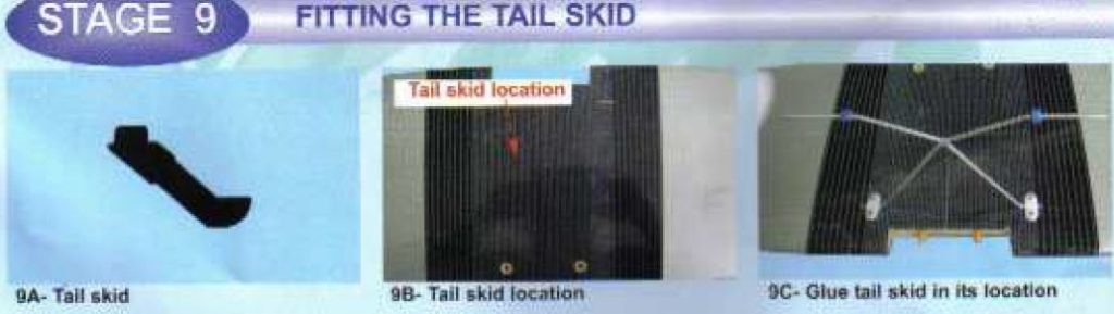
Here is where it should go, just epoxy it in there and it will be fine.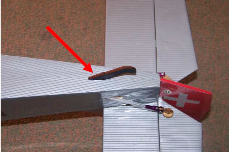
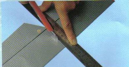
Fitting the horizontal and vertical stabilisers is the next task. The pictures and instructions are very good, with nothing out of the ordinary to worry about. A good point is made here in the instructions; when trimming the cover, to enable you to glue the horizontal stabiliser, be careful not to cut into the balsa on the stabiliser as this will weaken it at this point. If you do score the balsa run some thin CA over the cut, this will help to reduce the weakening. These are fitted using 30 minute epoxy ensuring all is true and level.
Whilst the epoxy was setting I decided to fit the landing gear, this consists of pre bent main landing gear and two dummy struts. The dummy struts in my kit where not very well assembled with them being barely held together with what appeared to be CA.
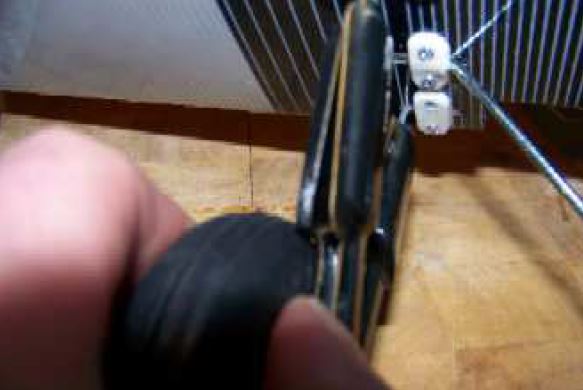
Quality of the dummy struts leaves a lot to be desired as they are badly cut and scruffy. I think I will remove them from my model but I am not sure yet.
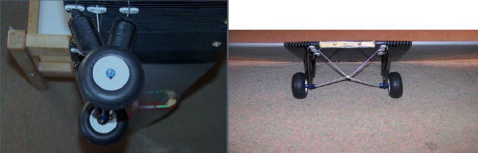
Apart from this the landing gear looks stout enough to withstand the odd heavier than you would like landing. The good size wheels should make taking off from short grass easy enough.
Under carriage now complete (apart from making it black) time to fit some servos to the fuse. I had chosen HS55’s for this model as they are pretty much bullet-proof, and then I stood on one which it didn’t like very much so I had a rummage and found a micro servo that last saw action in a Dynam Extra
330 so that had to do. The servo tray is very lightly built, which can only be made weaker when you put your screws in to retain your servos. I intend to beef it up in my model as there is a bit of flex when you operate the servos.
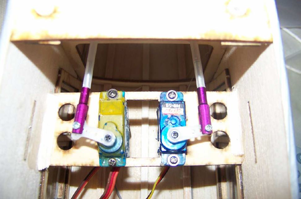
There is plenty of room in there so why such a flimsy tray? Nice touch here though, the servo tray has a wider slot in the middle so you can get your servo in without struggling to get the wire through, just slot it in and slide it sideways to the pre-drilled holes, easy. Connect up the clevises and job done.
 Pilot seats in place, glued on underside of battery tray before fitting.
So now on to the battery tray, after gluing on the pilot seats just slot the wooden battery tray into the slots and epoxy it in. I had to trim the tray in my model but no dramas here, but do remember to put the Velcro strap in first.
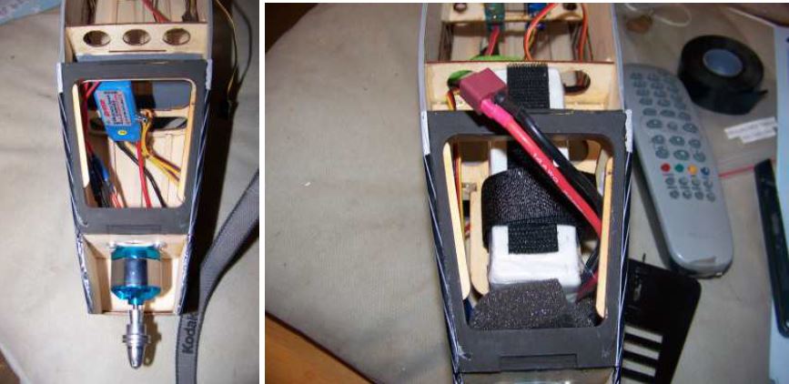
Sorry I forgot to take a picture of the battery tray, but here is a before and after, note the pre-installed brushless motor and esc.
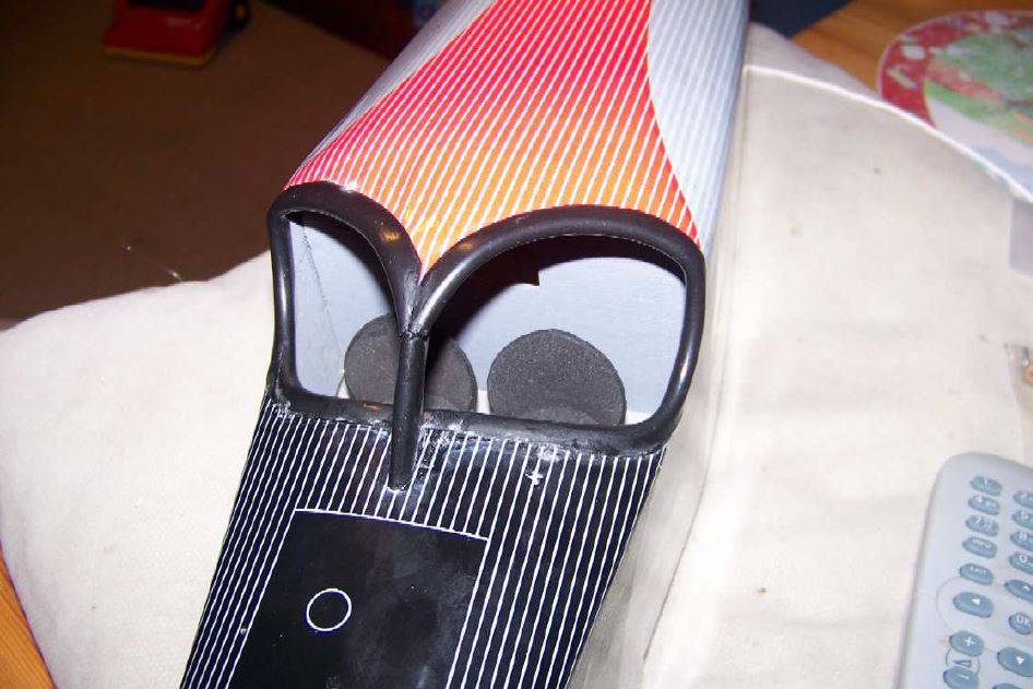
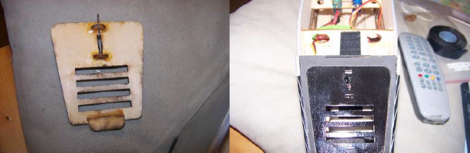
There is a neat little battery cover with spring clip which makes access to the battery nice and easy for changing the battery in the field.
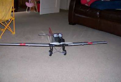
Now to fit the cowling, nice and simple make sure its pushed up the nose far enough to avoid fouling the pre-installed prop adaptor and one screw each side and one bang in the middle job done, looks good.
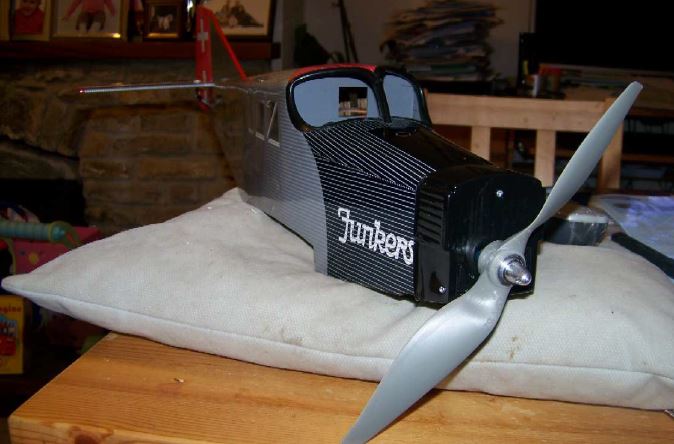
At this point I fitted the recommended prop, a 9×6, looks huge but that’s what it said.
I will look into getting a three bladed one later on to make it more scale.
Not much left to do now just bolt the wing on and check the C of G.
The recommended battery is a 1500 3 cell lipo, I have fitted a 2250 3 cell so I was expecting to be moving the battery pack about , but believe it or not the c of g was spot on , 75 to 80 mm from the leading edge at the root, spot on 75mm how jammy is that!
Just need some good weather for the maiden now.
Can’t wait; let’s hope she flies as good as she looks.
My verdict.
This is a very easy ARF kit to assemble and only took me about 3 hours ish; it is very good value for money, fuselage and wings are very well made with no glue missing. Some really nice touches and details too with only one or two minor niggles. This is one of Vmars new range of electric models with 5 or 6 other interesting ones just hitting the stores, I’m sure the little niggles will be addressed as they get feedback from customers. She is a pretty plane and one I would recommend for anyone wanting to get into semi scale stuff on a budget.
Good job VMAR .
RRP £79.95
Built up balsa wings and fuselage.
1225mm wing span.
Length 720mm
Weight 825g
Semi symmetrical airfoil
4 channel radio required.
Pre-installed brushless outrunner and 25 amp ESC.
Required to complete:
4x HS55 servos (or equivalent)
2x 70mm servo extensions.
It also says you need 2x 300mm extensions but I didn’t need them?
9×6 Prop,
1500 3 cell lipo.
30 minute epoxy
Thin cyno.